Original Brew.
Original blogs on AI systems, agents, news deep dives, technology teardowns.
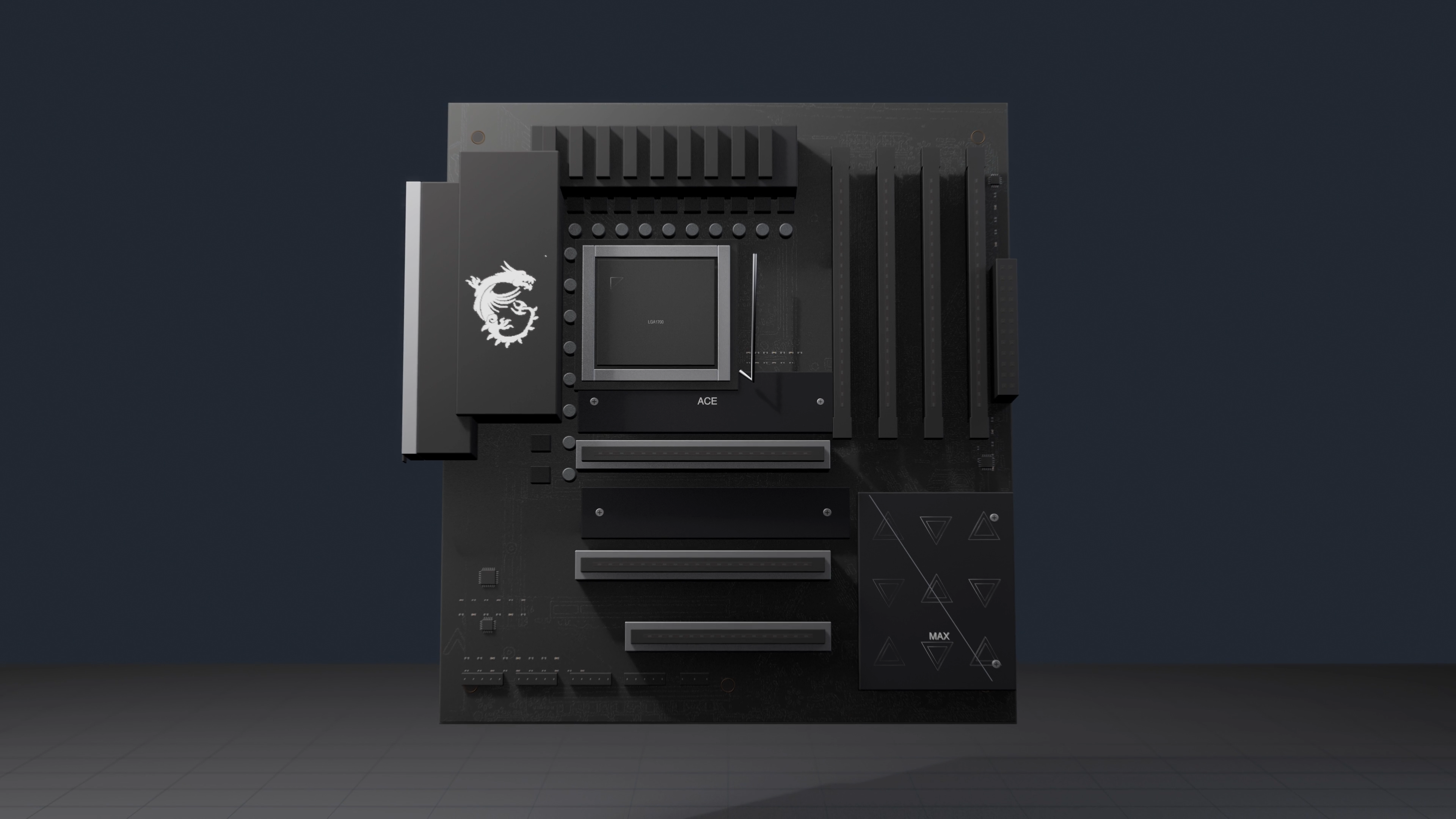
如何用 Codex + Blender 制作科普动画
同步观看解说视频:https://www.youtube.com/watch?v=unAazwa9YlI 我很喜欢看一些科普类的视频,尤其是动画精美的。给大众看的科普内容最怕的就是“干货满满”,毫无趣味,抓不住人的眼球。这时候,一个制作精良的动画能使内容变得生动、直观,而动画本身也很有审美价值。 这一点,在我了解到国外的Branch Education和国内的博主乔红Knot的作品之后,给我震撼更为强烈。 !Image: branch-education-example.pnghttps://jjxxiuscechxakmindos.supabase.co/storage/v1/object/public/newsletterimages/originals/original-3-zh/01-d5398327335d3899.png?v=d5398327335d !Image: qiaohong-knot-example.pnghttps://jjxxiuscechxakmindos.supabase.co/storage/v1/object/public/newsletterimages/originals/original-3-zh/02-453336a98e619752.png?v=453336a98e61 在我自己也开始做一些科普视频之后,便开始探寻这种视频是怎么做出来的。我了解到,Blender是其中一项常用工具。 它是一套完整的 3D 制作工具。你可以用它搭建一栋房子、拆解一颗计算芯片,或者展示血液如何流经心脏。它能为物体和摄像机制作动画、模拟物理系统、添加灯光与材质,并把所有内容渲染成完整的视频。 但 Blender 的强大,也让它的学习曲线变得非常陡峭。打开软件,映入眼帘的是密密麻麻的面板、修改器、材质、灯光、摄像机、关键帧和渲染设置。即使是入门,也需要看一系列教程,才能了解它的使用原理。 有没有什么方法,能让懒惰的人类(我)既能得到成品,又能不学习呢?当然有,毕竟AI都快取代人类了,区区Blender算什么。 这篇文章会为你展示这个工作流,并且分享我在其中踩过的一些坑和得到的经验。在这之前, 先展示几段完全通过 Codex + Blender 制作的视频,从始至终我都没有手动打开过Blender。 !Video: nvidia-gh100-structure.mp4https://jjxxiuscechxakmindos.supabase.co/storage/v1/object/public/newsletterimages/originals/original-3-zh/06-9d1a194bfb5bbbc4.mp4?v=9d1a194bfb5b NVIDIA GH100 的内部结构 !Video: house-construction.mp4https://jjxxiuscechxakmindos.supabase.co/storage/v1/object/public/newsletterimages/originals/original-3-zh/07-ef1fa615f105436d.mp4?v=ef1fa615f105 一栋房子是如何建成的 !Video: blood-flow-through-heart.mp4https://jjxxiuscechxakmindos.supabase.co/storage/v1/object/public/newsletterimages/originals/original-3-zh/08-1b35147db315245b.mp4?v=1b35147db315 血液如何流经心脏 !Video: car-engine.mp4https://jjxxiuscechxakmindos.supabase.co/storage/v1/object/public/newsletterimages/originals/original-3-zh/09-f81b34c436851116.mp4?v=f81b34c43685 汽车发动机如何工作 哪些事情可以交给 Codex 决定 即使只给出一条简单的提示词,例如: 请使用 Blender 制作一段教育视频,讲解 NVIDIA H100 的不同组成部分,并配上旁白和字幕。 Codex 也会前往官方网站收集资料,确定技术范围和讲解方式,再把视觉风格,包括真实感、材质处理、灯光、配色和镜头语言等,转换成 Blender Python 与 Geometry Nodes。它还会选择合适的 TTS 模型,并把字幕直接烧录进视频。 下面这个场景,就是使用 5.6 Sol High 一次生成的结果: !Image: h100-first-generation.pnghttps://jjxxiuscechxakmindos.supabase.co/storage/v1/object/public/newsletterimages/originals/original-3-zh/03-bffa710dc6f77252.png?v=bffa710dc6f7 哪些事情由你替 Codex 决定 这个画面看起来的确挺3D的。但如果把它与 Branch Education 的芯片讲解系列比较,完全不是一个级别。 提升品质的方法其实也很简单, 你只需要给 Codex 一段参考视频,让它仔细研究,它就会拆解其中的视觉语言:几何结构、材质、灯光、镜头运动、节奏、标签设计和细节层级等,并据此反向拆解视频制作,把成片的质量标准提高一个层次。 除此之外,还有几个重要决定需要你主动告诉Codex: - 视频应该多长? - 目标观众是谁?他们看完之后应该理解什么? - Codex 应该参考哪些文章、文件、视频、音频或其他资料来设计大纲和细节? 当我把 Branch Education 的视频交给 Codex 作为参考后,下一版的质量明显提升了一个层次: !Video: h100-reference-improved.mp4https://jjxxiuscechxakmindos.supabase.co/storage/v1/object/public/newsletterimages/originals/original-3-zh/10-c6c5184c40a52a69.mp4?v=c6c5184c40a5 先确定一帧的形态 制作 Blender 动画的成本挺高的。首先,Codex 需要消耗不少 token 来规划和协调整个流程;其次,Blender 渲染本身也会占用大量算力、内存和时间。一段细节丰富的 4K 动画,仅渲染就可能花费数小时。 因此,尽早确认视觉方向非常重要。你可以要求 Codex 只渲染 一张具有代表性的 4K 画面,并确保它包含最精细、清晰可读的细节,一个有代表性的标签,以及一条烧录在画面中的示例字幕。 先检查材质、灯光、构图、细节程度和字体排版。如果有任何地方不对,就让 Codex 修改场景。完整渲染之前多迭代几次样片,往往能省下后面数小时的返工。 对于英文旁白,我推荐两个免费选择: Kokoro-82M 和 Microsoft Edge TTS。Kokoro 可以在本地运行,英文声音自然、温暖而清晰;Microsoft Edge TTS 基于云端,更适合多语言脚本,对技术词汇的处理也相当不错。中文的话,我选择自己录。 让 Codex 寻找现成模版 对于某些主题,例如人体解剖,GitHub 上已经有质量很高的 Blender 模板。与其从零开始建模,不如站在一个成熟模板的基础上继续制作。这样一来,Codex 就能把更多精力放在讲解逻辑、动画设计和视觉打磨上,也更有机会产出高质量的视频。 例如,当我第一次让 Codex 制作一段解释血液如何流经心脏的视频时,结果是这样的: !Image: heart-from-scratch.pnghttps://jjxxiuscechxakmindos.supabase.co/storage/v1/object/public/newsletterimages/originals/original-3-zh/04-7e010b7f7c26216d.png?v=7e010b7f7c26 当我再给它提供Github上高质量的 Blender 模板作为参考后,结果变成了这样: !Image: heart-with-template.pnghttps://jjxxiuscechxakmindos.supabase.co/storage/v1/object/public/newsletterimages/originals/original-3-zh/05-162b4386ba9e25fb.png?v=162b4386ba9e 还是要尽量踩在巨人的肩膀上! Skill 分享 如果你懒得自己摸索的话,我已经把整套工作流整理成了一个 Skill:make-blender-education-video-skillhttps://github.com/sunxiayi/make-blender-education-video-skill,只要下载好blender,可以召唤它直接试试。 这个 Skill 总结了我在多次实验中学到的关键经验: - 开始制作前,Codex 会先询问视频长度、目标观众、学习目标、视觉风格和研究资料。 - 它会在 GitHub 上搜索可以复用的 Blender 工作流、模板和素材。 - 它提供了组织讲解结构、把视觉参考转化为风格说明,以及建立整套视觉系统所需的指导和脚本。 - 它只会先渲染一张具有代表性的画面,然后停下来等待你的确认,再制作完整视频。 - 它会准备英文旁白,并把英文字幕直接烧录到最终视频中。 不过这个skill只包含了英文的字幕和旁白,中文需要你自己迭代一下。它的价值在于是把我在反复试错中总结出的准备工作、检查机制和可复用步骤封装起来,你可以把它当作一个起点来进行迭代。
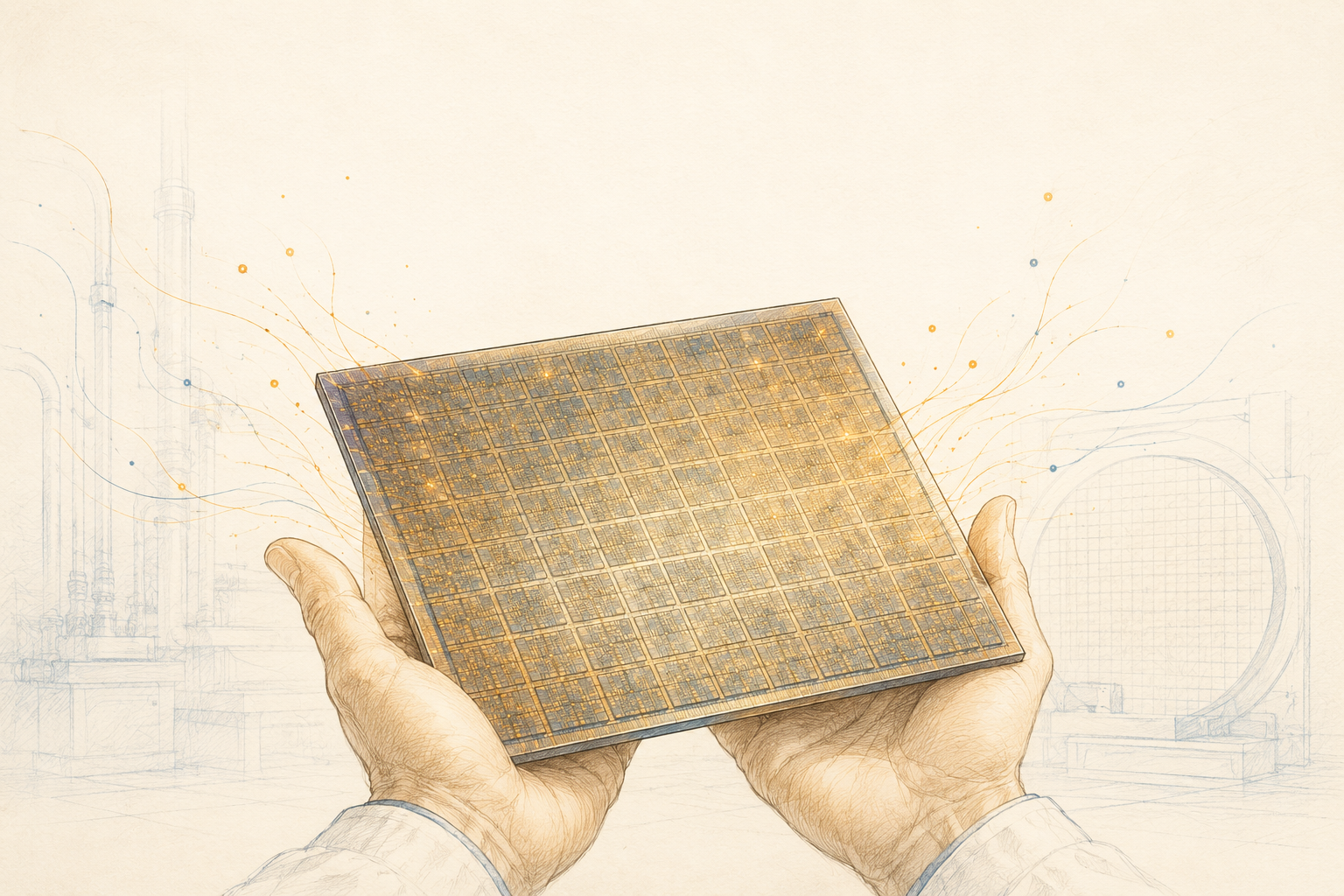
Cerebras:如何造一颗盘子大的芯片?
同步观看解说视频:https://www.youtube.com/watch?v=d469pDy8OKA !Image: wse3-wafer.jpghttps://jjxxiuscechxakmindos.supabase.co/storage/v1/object/public/newsletterimages/originals/original-2-zh/02-43788c5c3b315126.jpg?v=43788c5c3b31 上图所示, WSE-3, 是世界上最大的单片芯片,也是这篇文章的主角。第一次看到它的时候,我确实有点被「棒喝」住了:视觉冲击太大,脑子里一下冒出十万个为什么,比如: 为什么要造这么大一块芯片? 这么大一块 怎么 造出来? 它会遇到 什么 工程难题,又是怎么解决的? 这篇用视频、图片和文字一起讲清楚,它为什么要这么大,以及制造它必须翻过的三堵工程高墙。 一切的基础:WSE-3 芯片 Cerebras 的主要产品 WSE-3,是用一整张 12 寸晶圆做成的「超巨型芯片」。普通芯片生产时会把裸片一颗颗切开,而 Cerebras 则反过来——把裸片一颗颗用电线 连起来,让原本的切割线变成连接相邻裸片的数据通道。每行走线、每列也走线,整张晶圆被焊成一张不切割的 2D 网格:一共 84 块裸片,每块约 10000 个核心,每个核心一半是 48 KB 的 SRAM、一半是逻辑电路。 这种跨芯片连接是个新鲜玩意儿。它的专利里列了五种实现方案,我们以第一种为例讲讲。 !Image: lithography-basics.jpghttps://jjxxiuscechxakmindos.supabase.co/storage/v1/object/public/newsletterimages/originals/original-2-zh/03-73768e6b6a209c4b.jpg?v=73768e6b6a20 要理解它,先回顾一般的光刻工艺:一整片圆形硅片叫 晶圆;晶圆上做好的一块块电路叫 裸片;光刻时,光刻机把电路图案放在光掩膜上再投影到晶圆表面,而掩膜中心是和各裸片中心对齐的。 而这个专利的创新,是让光掩膜沿 X 或 Y 轴移动一点距离,对裸片做 偏移曝光,从而在相邻裸片之间形成连线。它完全复用了原有的光刻工艺,只是改了曝光位置,因此跨裸片通信远比传统的芯片间通信高效。 !Video: offset-exposure-cn.mp4https://jjxxiuscechxakmindos.supabase.co/storage/v1/object/public/newsletterimages/originals/original-2-zh/11-28dd2dac4b3f1ebd.mp4?v=28dd2dac4b3f 第二个不走寻常路的地方,是让每个核心里的 SRAM 与逻辑电路共存,而不是走 GPU 的老路。GPU 的绝大部分数据住在片外的 HBM 里,要经过硅中介板和多层焊点才能取到。而 WSE-3 的算力与存储在同一块裸片内、用铜线相连,带宽因此暴涨:主存带宽近 21,000 TB/s,而 B200 是 8 TB/s、H100 是 3.35 TB/s,差了几千倍。 !Image: memory-bandwidth.jpghttps://jjxxiuscechxakmindos.supabase.co/storage/v1/object/public/newsletterimages/originals/original-2-zh/04-f6ec5ef716e3a195.jpg?v=f6ec5ef716e3 内存墙与 roofline 模型 增加内存带宽能解决一个关键问题: 不要让计算核心等数据。大模型推理里,每生成一个 token 都要读取大量权重,很多时候瓶颈不是「算不动」,而是「数据喂不快」。这就是最经典的 内存墙 问题。 描述它最有名的模型叫 roofline model,它论述了三个量之间的关系:算力(FLOP/s)、带宽、以及 算术强度 (每搬一字节能做多少次运算)。 这里面的算力和带宽都比较好理解,算力,指的是FLOP/s,每秒浮点运算次数,它一般由计算单元数量、频率、每个周期运算量、数据精度等决定。带宽,指的是内存系统每秒能把多少数据送到计算单元上。算术强度是什么呢?它是FLOP ÷ Bytesmoved —— 即每搬一字节数据能做多少次运算。这个数重要的原因是,它决定了计算的实际峰值。Roofline equation中,计算性能由峰值算力,或者带宽 x 算术强度,两者的最小值决定。 Achievable performance = min peak FLOPs, BW × 算术强度 !Image: roofline-model.jpghttps://jjxxiuscechxakmindos.supabase.co/storage/v1/object/public/newsletterimages/originals/original-2-zh/05-c9e76fe547854cd5.jpg?v=c9e76fe54785 怎么理解这个公式呢?看图,纵轴是计算峰值速度,横轴是算术强度。上面的横线是计算的peak FLOPS。下面的斜线中,斜率是带宽。ridge是两条线的交点,也是memory-bound与compute-bound的分界点。在ridge左边,你可以通过增强算术强度来达到更高的算力,这说明GPU算力吃不满,瓶颈是内存带宽。在ridge右边,就算增强更多的算术强度,也会被算力峰值所限制。这说明内存已经能喂饱计算单元,瓶颈变成峰值算力。 而所谓内存墙问题,说的就是AI芯片所运行的任务,位于ridge的左边,也就是memory-bound。而大多数的AI推理场景,都位于ridge的左边。 AI推理大概是怎么工作的呢?在生成第 N 个 token 的时候,要读整个模型的权重 + 之前token 的 KV cache,只为算一个 token 的输出。这里明显计算少、数据搬运多。在一些模型的场景里,计算峰值的释放率甚至不到百分之零点几。这个洞察使很多厂家纷纷下场,比如Groq公司的芯片LPU,TPU专门为推理设置的芯片TPU 8i,还有WSE-3等,都想尽办法,加强内存带宽,使得算力的性能能够尽可能地释放。 失败的旧梦,来到了合适它的时代 造大芯片这个梦,几十年前就有人做过。 上世纪 80 年代,Gene Amdahl——IBM System 主机的核心设计者——就想直接做一颗接近晶圆级的「超级芯片」,把大部分数据留在处理器本身。他的公司 Trilogy 融了当时硅谷史上罕见的 2.3 亿美元。但公司八字不太好:建厂遇上暴雨、空调受损、洁净室进灰;高管患脑瘤去世;Amdahl 本人还卷入车祸和法律纠纷。当年的封装、散热、测试工艺又远不成熟,这事最终黄了。 几十年后,这个失败过的旧梦,终于等到了合适的时代。但技术上依然困难重重。Cerebras 的招股书上就颇为煽情地写道: Nobody knew how to yield a chip 58 times larger than the leading GPU. Nobody knew how to deliver power to a chip the size of a dinner plate without melting the motherboard. Nobody knew how to package such a big chip without cracking it. Nobody knew how to cool a chip of this size, with air or water, without the coolant getting warm before it reached the other side. Nobody knew, and we didn't know. —— Cerebras 招股书(S-1) 那接下来呢,我们就跟随着这几段话,去拆解一下大芯片制造的难点,以及困难是被怎样克服的。 第一难点 —— 良率 yield,良率,就是生产出来的芯片里,合格芯片的比例。 大家都玩过扫雷吧?地图越大,藏的雷越多。在一小块 3×3的格子里,可能一颗雷都没有,你轻松通关。可要是把地图放大到整个屏幕,雷必然遍地都是。芯片也一样——晶圆越大,里面的缺陷也多越多。缺陷是没法避免的——灰尘掉落、化学不均匀、光刻偏差,都会造成缺陷,传统的芯片设计中,一般会把坏的裸片进行降级卖或报废。但是对于大芯片来说,这种策略肯定不奏效,一万张晶圆里,挑不出一张是完好的。 为了解决这个问题,Cerebras采取了几招。 首先,它把每颗核心做的非常小,只有0.05平方毫米。这样的话,如果一颗核心有坏点,需要报废,它所波及的范围至少没有这么大。对比来说呢,GPU 上坏一个点,就得关掉一整个单元,这个单元的面积(6.2平方毫米)比WSE-3 上被关掉的核心面积大得多。 另外,它们保留了大概7%左右的核心作为冗余,在生产测试过程中,发现一些核心坏的时候,就会重新配置通信网络,绕开坏点,使用冗余通信路径。 !Image: yield-redundancy.pnghttps://jjxxiuscechxakmindos.supabase.co/storage/v1/object/public/newsletterimages/originals/original-2-zh/06-b07bf54c129ad863.png?v=b07bf54c129a 通过这种方案,它们不仅启用了93%的的核心,还实现了将近100%的良率。 第二难点 —— 供电 Cerebras为它们的大芯片定制了一个服务器,叫CS-3。它提供了芯片运行所需的电力、散热、互联、系统管理。一台CS-3整机功耗为25kW,大约需要25000A的电流。 25000A 是什么概念?家用电闸大概能承受约40A的电流,25000 A约等于625个家庭的总电闸全开、电流加在一起。也就是说,一个小区的瞬时用电电流,都集中在一台服务器上。 这么大的电流,需要通过分层降压的方案,远处用高电压小电流,快到芯片才一级级降到约1V的电压、把电流放大。 电流快到芯片的时候,采取了一种比较先进的供电方案,叫做Vertical Power Delivery,垂直供电。 !Image: lateral-power.pnghttps://jjxxiuscechxakmindos.supabase.co/storage/v1/object/public/newsletterimages/originals/original-2-zh/07-a3b0ed68d147ff0e.png?v=a3b0ed68d147 为了与横向供电做对比,大家可以先看这块AMD的GPU芯片,中间就是AMD的GPU,而右边这几排,是负责供电的,这些供电单位会把电压一步步降下来,最终降到GPU适合工作的范围。我们可以看到这里的供电是横向的,而且电线需要在PCB板上以很大的电流跑一段距离才会供电到GPU。 但是对于25000 A这么大数字的电流,这个方案至少有两个比较严重的缺陷。首先,如果电压在封装外部转换完了,最终以大电流、小电压的形式走了比较长的一段距离,那么由于电压已经很低,压降,也就是电压被这段线路“消耗掉”的部分,它的容忍度就很小。根据压降的公式计算(Vdrop = I × R),在25000A 下,哪怕路径电阻只有0.00001欧姆,那么压降也有0.25V。芯片的核心电压在1V左右,那么0.25V的消耗,就算25%的电压损失。 另外,这些掉了的电压,会转换为热量。根据功率的公式(P=IV),这0.25V的消耗,会产生0.25V 25000A=6250W的热量,产生很大的局部热量。 所以,为了使最后一段供电的路径尽量的短,Cerebras用了Vicor的供电方案,它把最后一级供电模块,也就是那个把电压调小的转换器,做得离 GPU 的封装非常非常的近,这样就减少了大电流要传输的距离。同时,它用垂直供电代替了横向供电,也就是说把电流转换器直接放在处理器下方,相对于横向供电来说进一步减短了传输的路径。 !Image: vertical-power.jpghttps://jjxxiuscechxakmindos.supabase.co/storage/v1/object/public/newsletterimages/originals/original-2-zh/08-ef22ca0ec134e268.jpg?v=ef22ca0ec134 第三难点 —— 散热 25kW的大功率机器,散热也是个大问题。一般数据中心的服务器散热,分为风冷和液冷两种。因为空气的携热能力比较弱,而液体的携热能力强得多,所以高功耗、高热密度场景更适合液冷。而WSE-3的超大面积,又给液冷加上了独特的挑战。 首先,大多数物体受热都会产生一定的膨胀。热膨胀的基本公式是ΔL=α⋅L⋅ΔT,这里: - ΔL:长度变化 - α:材料的热膨胀系数 - L:原始长度 - ΔT:温度变化 物体受热后的长度变化,与原始长度成正比。因此,普通 GPU的裸片小,热胀冷缩有限。而尺寸放大后,哪怕温差不大,膨胀位移也会变得很明显。在芯片封装中,几十微米的膨胀都会导致危险的后果,因为芯片里的互连、焊点等本来就是微米级甚至更小的尺度。 而且,这么大一块晶圆,不同地方的温度有高有低,温度一不均匀,不同区域热膨胀长度不同,就会产生机械应力。热的地方,想膨胀更多,而冷的地方,则限制了这种张力,内部互相拉扯,晶圆可能会出现翘曲。 但其实,最最危险的一点,在于热膨胀系数。在上面的公式中,这个α,就是材料的热膨胀系数,它表示温度每升高 1°C,材料长度相对于原长度会增加多少。硅的热膨胀系数比较低,大约2–3 ppm/°C,而铜和PCB的热膨胀系数更高,大约15-17ppm/°C。假设两种材料升温60摄氏度,膨胀差能达到160 μm,这大约是一根人头发的厚度,但足以把焊点撕裂、把封装拉碎。对比起来,普通GPU的裸片只有 3 cm,同样温度升高,膨胀差距才几μm,焊点的弹性能够消化。 这些挑战啊,促使Cerebras研发了一种非常独特的封装,它也是CS-3 的核心,Engine Block。它为 WSE-3 这整片晶圆级别的芯片固定并提供供电、冷却等方案。 !Image: engine-block.jpghttps://jjxxiuscechxakmindos.supabase.co/storage/v1/object/public/newsletterimages/originals/original-2-zh/09-c2f8f68980d2afd8.jpg?v=c2f8f68980d2 !Image: engine-block-layers.pnghttps://jjxxiuscechxakmindos.supabase.co/storage/v1/object/public/newsletterimages/originals/original-2-zh/10-94f0c2ffebe43f73.png?v=94f0c2ffebe4 在这个示意图里可以看到,它由冷板、芯片、PCB,以及它们中间的连接器构成。我们把它横过来看的话,冷板在最上方,PCB在最下方,芯片被夹在中间,芯片与PCB和冷板之间之间,由于热膨胀系数的不同,都采用了特殊的连接层。连接层的设计思路是,竖直方向负责干正事(要么传热、要么导电),横向留出「可滑动」的自由度去吸收热膨胀系数不同导致的形变。 比如说,他提到的在晶圆和铜板之间这层会滑动的热界面材料,在冷板那一面的材质,是铟(indium),负责导热,在晶圆那一面,是一层极薄的PTFE(也就是特氟龙),负责减少摩擦。晶圆和铜板压在一起,但没有焊接,可以互相滑动。 在晶圆和PCB之间,则用一层埋着导电颗粒的硅胶橡胶模连接。这些导电颗粒在竖直方向上互相接触,发挥导电的功能,水平方向上也能彼此滑动。 所以说,Engine Block 本质上不是一个普通封装,而是一个把供电、散热、机械支撑和信号连接全部重新设计过的支持晶片级芯片的系统。 定制化的包袱 说到现在啊,我们已经不知不觉地说了好几项创新了,比如: - 芯片的面积 - 切割线改电路线 - 大芯片、高良率 - 极小的核心 - SRAM直接做在核心里,带宽极高 - engine block零焊点 - VPD垂直供电 等等等等。 它的这些创新,也实实在在带来了推理速度的飞升。在公开benchmark里,它的每秒output token数比GPU快了几十倍。不过说完它的技术创新,再说说它带来的代价——定制化。 首先,裸片之间的连接的技术落地,是Cerebras与台积电之间的独家合作,这点它在招股书里也承认:它专用工艺不易移植到另一家代工厂。那一旦台积电产能紧张,它就没有第二个可以选择的代工厂。 在供电方面,也很类似。之前说的垂直供电由Vicor公司提供,这种定制的电源提供服务,在短期内很难找到备胎替换。Vicor公司在Q1的earningcall中说道它们的产能已经到了极限,那如果Vicor的产能有一天跟不上,Cerebras也跟着被卡脖子。 在液冷方面,CS-3因为功率密度高,需要更低的进水温度,这意味着,运营商需要提供更大的泵、更粗的水管、冷却能力更强的CDU、更高流量的接头,这些都与标准的机房不兼容,需要额外定制。 这些事实都隐含着一个方向,那就是,Cerebras走的定制路线,会限制它的扩张速度。关键节点只有单一合作商、塞不进普通的商品机房、供电和液冷都需要重新定制。那能不能将它最终变成可规模化的供应链,会最终决定它的发展进程有多稳定。

SpaceX猎鹰一号致命失败中的蝴蝶效应
同步观看解说视频:https://www.youtube.com/watch?v=FvgomsNjlYA 最近SpaceX上市,各大媒体纷纷回顾它的来时路,我就在想有没有什么刁钻的角度讲讲别人没讲过的东西。做资料调查的时候,发现猎鹰一号的几次失败原因挺有趣的——对我来说,航空航天是个比较陌生的领域,它的失败模式对我来说也很新鲜。这篇文章细数了几次发射失败是从怎样的小小细节开始,再碰上特殊的航天环境,造成了发射的失败。写完这个,更加敬佩这些造火箭的勇士,面临着太多未知与不可预测不可知,一个个突破。 SpaceX 猎鹰一号在第四次发射时终于成功入轨,这也是它第一次发射成功。但猎鹰一号通往轨道的路一波三折——在那一刻之前,它已经失败了三次,而这三次失败,把马斯克和 SpaceX 都逼到过绝境。 也许你听说过,这三次失败的原因,都是一些很小的细节引起的。在这篇文章里,我想带大家捋一捋每一次失败的根因,以及每一个小细节如何通过蝴蝶效应,最终滚雪球般酿成灾难。我自己查资料的时候,还有点担心内容太硬核;但这些小细节牵出的连锁反应实在太有意思,也让我对那句"魔鬼藏在细节里"有了更深的体会。 第一次失败:一颗被腐蚀的螺母 2006 年 3 月 24 日,被寄予厚望的猎鹰一号迎来历史性的首飞。但起飞仅约 33 秒后,一级发动机突然失去推力,飞行器随之失控,发射失败。随后,由美国国防高级研究计划局(DARPA)牵头的深度残骸分析,揭示了一个非常隐蔽的工程盲区。 !Image: b-nut.webphttps://jjxxiuscechxakmindos.supabase.co/storage/v1/object/public/newsletterimages/originals/original-1-zh/02-894363ec94e58f54.webp?v=894363ec94e5 根本原因是这个不起眼的小零件—— B-nut 。它是一种专门用于航空、汽车等领域、装在管路接头上的 连接螺母 。外部有六角扳手面,内部是圆形螺纹孔,作用是把管子拧接到接头上,提供夹紧力、形成密封,防止燃油泄漏。 猎鹰一号首飞时,正是这颗螺母的内部被严重腐蚀,进而开裂。本该被密封住的燃料开始泄漏,顺着推力室外壁流下。泄漏的高压燃料迅速被尾焰引燃,大火几乎在瞬间烧穿了控制管线,最终导致发动机在起飞后 34 秒彻底停机。这就是猎鹰一号首飞的悲剧。 蝴蝶效应在这里体现得淋漓尽致:一颗螺母的腐蚀,导致了整台发动机停机。那么,这颗螺母为什么会腐蚀呢? 这颗螺母本身是铝制的,而它连接的管子是不锈钢的。两种不同的金属放在一起,再加上发射基地位于太平洋赤道附近的海岛上——温暖、潮湿,空气里满是带盐分的水雾——大问题就来了。这其实就构成了一个电池。盐水导电;不锈钢电位高、性质稳定,可以看作正极;铝电位低、容易失去电子,可以看作负极。于是就像电池缓慢放电一样,这颗铝螺母被一点点腐蚀掉了。 !Video: corrosion-cn.mp4https://jjxxiuscechxakmindos.supabase.co/storage/v1/object/public/newsletterimages/originals/original-1-zh/04-a189b3748386691c.mp4?v=a189b3748386 修复办法也很简单。为了根除隐患,SpaceX 在后来的设计里把所有铝螺母都换成了不锈钢螺母。这样管子和螺母就是同一种金属,彼此之间没有电位差,这种致命的"电池效应"自然也就不会再发生。 第二次失败:死亡摇摆 时隔一年,2007 年 3 月 21 日,猎鹰一号进行第二次发射尝试。这一次,一级飞行表现相当出色。但在级间分离时,一级火箭发生回弹,轻轻磕到了二级火箭的铌合金发动机喷管。这次物理碰撞非常轻微,却给二级引入了一个微小的偏差。也正是这个微小的偏差,让命运的齿轮再次转动,蝴蝶效应又一次启动。 为了纠正这个偏差,二级火箭的控制系统开始介入。假设飞行路径往左偏了一点,控制系统就会把发动机喷管摆动一个小角度,把路径往右调回来。但此时火箭已经进入二级阶段,助燃剂用掉了一半——也就是说,储箱有半箱是空的。在这个调整过程中,箱内的液氧开始晃动;因为惯性,它猛地拍向储箱另一侧,导致重心偏移。控制器又捕捉到了这个偏移,判断需要往反方向再调,于是液体又向另一边晃……根据记录,这种控制系统与液体之间的"死亡摇摆",从起飞后约 4 分 20 秒开始显现,并持续了三分多钟。 更糟糕的是,发动机为纠偏而摆动的频率,恰好和半空储箱里液氧晃动的节奏撞在了一起。 这是什么意思呢?你可以把这些液氧想象成在荡秋千:每次它刚要开始晃,发动机就恰好顺着同一个方向再推它一把。于是晃动越来越大。在强大的离心力作用下,液氧被甩向储箱四周的内壁,中间则空出一个巨大的漩涡。这时,二级发动机再也吸不到液氧,而是直接吸入了用来给储箱加压的气体。在航天工程里,这种情况非常致命:发动机不仅失去了助燃剂,还会因为吸入气体而"空转"。最终,保护机制强制熄火,火箭失去动力,坠落而下。 !Video: death-wobble-cn.mp4https://jjxxiuscechxakmindos.supabase.co/storage/v1/object/public/newsletterimages/originals/original-1-zh/05-f23c95117563b9c3.mp4?v=f23c95117563 这背后的物理,跟我小时候听过的一个故事很像:英国士兵过桥,把桥踩塌了。1831 年,在英国的布劳顿吊桥上,士兵们迈着整齐划一的步伐走过,而他们的踏步频率,恰好与这座桥的固有振动频率撞在了一起,桥就塌了。是不是很耳熟? 一个频率与另一个频率相撞,产生谐波振荡,最终酿成灾难。 !Image: ring-baffles.webphttps://jjxxiuscechxakmindos.supabase.co/storage/v1/object/public/newsletterimages/originals/original-1-zh/03-11dea404037e7b79.webp?v=11dea404037e 为了根治这个问题,工程师们在二级液氧储箱内部加装了物理的环形防晃挡板(ring baffles)。这些挡板增加了流体阻尼,减小了液体在箱内的晃动幅度。他们还修改了飞行控制软件的控制逻辑,人为调整控制频率,确保控制系统的频段与流体晃动的自然频率拉开足够安全的距离。这就阻断了那个反馈环路——越晃越高、一环喂一环的失控循环。 就这样,又一次,一个"半瓶水晃来晃去"的蝴蝶效应,摧毁了一枚价值数千万美元的运载火箭。 第三次失败:几滴残留的燃料 第三次失败,源于发动机冷却机制的一次升级。我们知道,大多数金属的熔点都在 2000°C 以下,但发动机点火时,燃烧室内的温度可以轻松突破 3000°C。没有相应的冷却机制,发动机壁根本扛不住这个热量。有趣的是,这里用的冷却剂,就是燃料本身——煤油。用燃料来做冷却。 它是这样工作的:燃料箱里的煤油在涡轮泵加压下,进入发动机壁内的冷却通道——这些通道由数百根极细的、薄壁的金属管紧密焊接而成。燃料绕着喷管和燃烧室流动,一路吸收热量。于是它一边给燃烧室降温,一边把自己预热成"待燃"的燃料。这种热量回收的技巧,就叫 再生冷却 。 !Video: regenerative-cooling-cn.mp4https://jjxxiuscechxakmindos.supabase.co/storage/v1/object/public/newsletterimages/originals/original-1-zh/06-5ef509c3b75d4013.mp4?v=5ef509c3b75d 那问题出在哪儿呢?还是在级间分离的时候。一级火箭完成了使命,不再向喷管输送新燃料。但是——魔鬼藏在细节里——在喷管壁的冷却通道里,还残留着一些煤油。周围滚烫的金属壁继续加热这些残余煤油,让它迅速汽化、膨胀。即便一级的主阀门和涡轮泵都已经关闭,这些膨胀的残余燃料依然被挤进燃烧室,与残余的液氧继续发生小规模燃烧。 结果就是:在关机指令下达后的几秒钟里,发动机并没有完全熄火,而是继续喷出一小股微弱的推力——也就是 残余推力 。正因为这股推力,一二级分离时,一级火箭仍在往前冲,最终追尾撞上了二级,导致发射失败。 更让人惋惜的是,这个现象在地面根本测不出来。在地面,大气压比这股残余推力所能产生的燃烧室压力更大,于是这股微弱的内部推力被外部大气压压制住了——看上去火箭已经完全关机。只有在近乎真空的太空里,没有任何外部大气压来对抗燃烧室的室压,这股残余压力才真正转化成驱动火箭前行的推力。 谈到这次失败,马斯克后来满怀懊悔地表示,如果当时在软件里多加一秒钟的等待时间,这场悲剧本可以避免。而最终的修复措施,竟然完全没有任何硬件改动——他们只是改了几行代码,加了大约 3.5 秒的倒计时,等推力归零。仅此而已。 至暗时刻 三次失败之后,马斯克和 SpaceX 进入了至暗时期。三次猎鹰一号发射尝试,烧光了一亿美元。特斯拉也面临严重的供应链危机。再加上全球金融海啸让投资全面收紧,更别提 SpaceX 这种高风险的硬核项目。马斯克本人还在此期间经历了婚姻破裂,一度连自己的房租都付不起,不得不向朋友借钱。 但英雄总有他的过人之处。也正是在这个时候,马斯克贡献了职业生涯中最具领导力的时刻之一。据前员工回忆第三次失败那天:当画面定格在火箭解体的瞬间,整个任务控制中心陷入死一般的沉寂。已经连续工作超过 20 个小时、极度疲惫的马斯克,走到团队面前,向全体员工讲话。他坦承了失败,紧接着说道: "对我个人而言,我永远不会放弃,我是说永远。只要你们和我站在一起,我们就一定会赢。" —— 马斯克,第三次失败后对 SpaceX 团队 之后,故事迎来了戏剧性的逆转。猎鹰一号的第四次发射终于圆满成功。从那以后,SpaceX 一路拿下 NASA 的合同,开始研发猎鹰九号、星舰、龙飞船,以及之后的一切。 最后,用马斯克在《60 分钟》访谈里的一句话收尾。第一次看到时,我确实被打动了。希望在马老板的带领下,有朝一日我也能有机会亲眼去火星看看。哪怕是单程的,也行。 !Video: musk-never-give-up-cn.mp4https://jjxxiuscechxakmindos.supabase.co/storage/v1/object/public/newsletterimages/originals/original-1-zh/07-ea99f2542592fd79.mp4?v=ea99f2542592
How to use Codex + Blender to make educational animations
Blender has always felt like one of those tools you need to “properly learn” before you can make anything useful. It is a full 3D production tool to model a house, open up a computer chip, or show blood moving through the heart. It can animate objects and cameras, simulate physical systems, add lighting and materials, and render everything as a finished video. That range is also what makes Blender intimidating. Open the app and you face a wall of panels, modifiers, materials, lights, cameras, keyframes, and render settings. Even a simple educational animation can turn into a small production: research the subject, model the scene, animate it, write the narration, generate captions, render thousands of frames, and hope the audio still lines up at the end. Thanks for reading! Subscribe for free to receive new posts and support my work. But now with the help of AI agents such as Codex, you could use plain English and finish high quality videos without even opening the app. With proper prompts and workflows, Codex could research the subject, plan the scenes, write Blender Python, build and animate the 3D elements, generate narration and captions, manage the renders, and check the final export with Computer Use. Before diving into the details of the workflow, I want to first show you the videos I made using Codex + Blender, without opening the Blender app and with zero knowledge on how to make a scene manually. !Video: insidenvidiah10060senglishkokoro4kv1 1080p.mp4https://jjxxiuscechxakmindos.supabase.co/storage/v1/object/public/newsletterimages/originals/draft-msjc2dho/02-5d37a44af41624ef.mp4?v=5d37a44af416 Internals of NVDIA GH100 !Video: howatypicalamericanhouseisbuilt1080pvimeov1 1080p.mp4https://jjxxiuscechxakmindos.supabase.co/storage/v1/object/public/newsletterimages/originals/draft-msjc2dho/03-a480c67d7619b074.mp4?v=a480c67d7619 How to build a typical American house !Video: howtheheartpumpsbloodv460sbilingual4kv1 1080p.mp4https://jjxxiuscechxakmindos.supabase.co/storage/v1/object/public/newsletterimages/originals/draft-msjc2dho/04-f65508c79032b93e.mp4?v=f65508c79032 How the blood flows through the heart !Video: howafourstrokeengineworks4knospeedv1 1080p.mp4https://jjxxiuscechxakmindos.supabase.co/storage/v1/object/public/newsletterimages/originals/draft-msjc2dho/05-e735935bba1751a0.mp4?v=e735935bba17 How a car engine works The workflow is not complicated. However, there are indeed a few gotchas that are only obvious after multiple rounds of trial and error. Dive Into The Workflow 1. What Blender can decide for you Even with a simple prompt, such as: Please make an educational video using Blender to show different parts in NVDIA H100, with narratives and subtitles. It would go to the official website to gather all the details, then define the technical scope, an explanatory pattern, translate the visual stylerealism, material treatment, lighting, palette, camera language etc to Blender Python and Geometry Nodes. It would also choose a TTS model and bake in subtitles. In this example, one-shot with 5.6 Sol High results in the following scene: !1.webphttps://jjxxiuscechxakmindos.supabase.co/storage/v1/object/public/newsletterimages/originals/original-3/01-10224ad4c54314de.webp?v=10224ad4c543 2. What you should decide for Codex That’s a valid 3D scene. However, put it next to a high-quality production like Branch Education’s chip explainer series, though, and they are completely different animals. Thanks to the multi-modality capabilities of the model, all you need to do is to give Codex a reference video and ask it to study the visual language closely: the geometry, materials, lighting, camera work, pacing, labels, and level of detail, to reverse engineer the video and raise the quality bar for the details. Aside from that, you still need to make a few important decisions: - How long should the video be? - Who is the target audience, and what should they understand by the end? - Which articles, files, videos, audio, or other references should Codex use to shape the outline and details? Codex can suggest defaults, but those defaults are guesses. A vague brief gives Codex room to make choices you may not like, and it is better to give it clear instructions for those questions. Once I give Codex a reference video of Branch Education, the next video quality is another level: !Video: h100photorealsample4kreviewv1 1080p.mp4https://jjxxiuscechxakmindos.supabase.co/storage/v1/object/public/newsletterimages/originals/original-3/02-e75cc3295b9dbec6.mp4?v=e75cc3295b9d 3. Get the scene right before the full render Producing a Blender animation is expensive in two ways. Codex may use substantial tokens to plan and coordinate the work. Blender then needs significant computing power, memory, and time to render it. A detailed 4K animation can easily take several hours. That makes early visual approval essential. Ask Codex to render exactly one representative 4K frame containing the finest readable detail, a representative label, and a sample burned-in subtitle. Review the materials, lighting, composition, level of detail, and typography. If something feels off, ask Codex to revise the scene. Repeating this process before the full render can save hours of rework later. For voice-over, if you are not planning to record yourself, I highly recommend two options: Kokoro-82M and Microsoft Edge TTS. Kokoro runs locally and offers natural, warm, clear English voices. Microsoft Edge TTS is cloud-based, works well for multilingual scripts, and handles technical vocabulary reasonably well. 4. Let Codex look for existing Blender resources For some subjects, such as human anatomy, high-quality Blender templates already exist on GitHub. Starting with a well-built template gives Codex a stronger foundation than modeling everything from scratch. It can then focus more on the explanation, animation, and visual polish, improving the chances of producing a high-quality video. For example, when I asked Codex to create a video showing how blood flows through the heart, its first attempt looked like this: !2.webphttps://jjxxiuscechxakmindos.supabase.co/storage/v1/object/public/newsletterimages/originals/original-3/01-77908734bedf2ef1.webp?v=77908734bedf After I gave it high-quality Blender templates to reference, the result looked like this: !3.webphttps://jjxxiuscechxakmindos.supabase.co/storage/v1/object/public/newsletterimages/originals/original-3/02-7775e09fa9112290.webp?v=7775e09fa911 It is always a good idea to stand on the shoulders of giants instead of reinventing the wheels everytime. The skill to get started Enough talking. I’ve packaged the workflow into a skill: make-blender-education-video-skillhttps://github.com/sunxiayi/make-blender-education-video-skill. The skill captures the most important lessons from my experiments: - Before starting, Codex asks about the video’s length, audience, learning goal, visual style, and research sources. - It searches GitHub for reusable Blender workflows, templates, and assets. - It includes guidance and scripts for structuring the explanation, translating a visual reference into a style brief, and building the visual system. - It renders exactly one representative frame, then stops for your approval before producing the full video. - It prepares English narration and burns English subtitles into the final video. This skill will by no means produce a perfect video on the first try. Its value lies in capturing the setup, checks, and repeatable steps I learned through trial and error. Treat it as a starting point. Iterate on the brief, references, and visual direction until the workflow fits your topic and audience. And let me know what you’ve made from the skill - I’m curious to hear.
The World's Largest Chip: Why Cerebras Built It, and How
The first time I ran into the Cerebras WSE-3, I had to look twice. It’s a single chip about the size of a dinner plate: 21.5 cm on a side, comfortably bigger than my face, and it holds the record for the largest chip ever made. Why would anyone build a chip this big? How do you even manufacture something that large without it falling apart? And what actually breaks when you try? The why, the how, and the what-breaks: those three questions are what this post is about. !wse3wafer.jpghttps://jjxxiuscechxakmindos.supabase.co/storage/v1/object/public/newsletterimages/originals/original-2/01-1e4d76499f543a7b.jpg?v=1e4d76499f54 The Cerebras WSE-3, one wafer, uncut, held like a serving tray. Part One: The chip itself Cerebras’s flagship is the WSE-3 Wafer-Scale Engine 3, and the simplest way to describe it is a chip that never got cut up. A normal fab prints dozens of identical dies onto a 12-inch wafer and then slices them apart into separate chips. Cerebras does the opposite: it leaves the wafer whole and wires the dies together, turning the scribe lines the thin dead zones between dies into data highways. Every row and column gets connected, and the whole wafer becomes one continuous 2D mesh: 84 dies, roughly 10,000 cores each, with every core split half-and-half between SRAM 48 KB and logic. That “don’t cut, connect” move is the genuinely novel part. The patent lists five ways to pull it off; the animation below walks through the first. If that didn’t quite land, it helps to back up to how ordinary chip-printing works. The round silicon disc is the wafer. Each finished block of circuitry on it is a die. During lithography, a scanner projects the circuit pattern off a photomask onto the wafer, lining the mask up over one die at a time. !Video: LithoBasicsEN.mp4https://jjxxiuscechxakmindos.supabase.co/storage/v1/object/public/newsletterimages/originals/original-2/02-29b0c5200e89bf25.mp4?v=29b0c5200e89 Cerebras’s trick is almost cheeky: nudge that photomask a hair along the X or Y axis an offset exposure so the pattern straddles the gap and prints wiring between two neighboring dies. Nothing about the lithography process changes; only where the mask lands. And that’s the whole point: talking across dies this way is far cheaper than stitching separate chips together on a board. !Video: OffsetExposureEN.mp4https://jjxxiuscechxakmindos.supabase.co/storage/v1/object/public/newsletterimages/originals/original-2/03-c659b3ef0793464b.mp4?v=c659b3ef0793 The second break from convention is where the memory lives. A GPU keeps most of its data in HBM stacks parked off to the side of the processor, reached across a silicon interposer and several layers of solder. The WSE-3 keeps compute and memory on the same die, joined by plain copper, and that single decision sends bandwidth through the roof: roughly 21,000 TB/s of main-memory bandwidth, against 8 TB/s on a B200 and 3.35 TB/s on an H100. Not a little more. Thousands of times more. !Video: MemoryEN.mp4https://jjxxiuscechxakmindos.supabase.co/storage/v1/object/public/newsletterimages/originals/original-2/04-74b7b8b963f7abf6.mp4?v=74b7b8b963f7 Part Two: Why bandwidth is the whole game Why is more bandwidth so important in AI inference? it does solve one very specific, very expensive problem: it stops the compute cores from sitting idle, waiting for data. When a large model generates text, producing each token means reading a mountain of weights, and the bottleneck usually isn’t “the math is too slow.” It’s “the data can’t arrive fast enough.” That’s the memory wall, and it’s the thing everyone in this business is fighting. The cleanest way to reason about it is the roofline model, which ties together three numbers: how fast you can compute FLOP/s, how fast you can move data bandwidth, and arithmetic intensity how many FLOPs you do per byte you move. Your real-world performance is whichever ceiling you hit first: raw compute, or bandwidth times intensity. Achievable performance = min peak FLOPs, bandwidth × arithmetic intensity !Video: RooflineEN.mp4https://jjxxiuscechxakmindos.supabase.co/storage/v1/object/public/newsletterimages/originals/original-2/01-ed6e8893c2d57cd3.mp4?v=ed6e8893c2d5 The roofline: the flat compute ceiling, the bandwidth ramp, and the ridge between them. Everything to the left of that ridge is memory-bound: the cores idle, starved for data. And here’s the kicker: nearly all AI inference lives on the left side. To generate token N, the chip has to read the entire model’s weights plus the KV cache just to compute that one token: trivial math, enormous data movement. In some cases you’re using well under one percent of the chip’s peak compute. Which is exactly why Groq’s LPU, Google’s inference TPUs, and the WSE-3 are all obsessed with the same thing: feeding the cores faster. Part Three: Had anyone even tried this? The dream of one giant chip isn’t new. Someone chased it decades ago, and it’s a genuinely strange story. Back in the 1980s, Gene Amdahl, the lead architect behind IBM’s System mainframes, set out to build a near-wafer-scale “super chip” that kept most of its data on the processor itself. His company, Trilogy, raised a then-record $230 million. Then everything that could go wrong did: a storm knocked out the fab’s air conditioning and let dust into the cleanroom, a senior executive died of a brain tumor, and Amdahl himself got tangled up in a car accident and a lawsuit. The packaging, cooling, and testing of the era weren’t close to ready either. The whole thing collapsed. Decades later, the failed dream finally met an era that could support it, but the engineering was still brutal. Cerebras’s own IPO prospectus put it about as dramatically as a legal filing can: Nobody knew how to yield a chip 58 times larger than the leading GPU. Nobody knew how to deliver power to a chip the size of a dinner plate without melting the motherboard. Nobody knew how to package such a big chip without cracking it. Nobody knew how to cool a chip of this size, with air or water, without the coolant getting warm before it reached the other side. Nobody knew, and we didn’t know either. Cerebras S-1 prospectus Four walls, then. Let’s take them one at a time. Wall One: Yield, a chip 58× bigger than a GPU Yield is just the fraction of chips that come off the line actually working, and the intuition for why it’s a nightmare here is easy to build: Think of Minesweeper. The bigger the board, the more mines it hides. A tiny 3×3 grid might have none, and you clear it without thinking. Blow the board up to fill your screen and mines are everywhere. Chips are the same. The bigger the wafer, the more defects: a speck of dust, a chemical non-uniformity, a lithography slip. Normally you just toss the bad dies and sell the good ones. But a chip that’s one giant die fails the instant a single spot goes bad. Out of ten thousand wafers, not one would come out flawless. Cerebras beat this with two moves. First, it makes each core absurdly small, just 0.05 mm², so a single defect only takes out a sliver of the chip. On a GPU, one bad spot can force you to disable a whole 6.2 mm² unit, over a hundred times larger. Second, it holds about 7% of the cores in reserve; when testing turns up dead ones, the on-chip network quietly reroutes around them and swaps in the spares. Net result: 93% of cores active, and yield close to 100%. Tiny cores plus redundant routing: how a “zero-yield” chip becomes shippable. Wall Two: Power, without melting the board Cerebras built its chip a custom home, the CS-3 server, and it draws 25 kW, on the order of 25,000 amps. Put it in household terms: it’s the current of every main breaker in about 625 homes, all maxed out at once, feeding a single server. Current that big gets delivered the usual way, by stepping the voltage down in stages: high-voltage/low-current far from the chip, dropping to around 1 V right at the die. But the flat, sideways layout most boards use has two nasty failure modes once you’re pushing 25,000 A. Problem one: voltage drop. From Vdrop = I × R, at 25,000 A even a hundred-thousandth of an ohm produces a 0.25 V drop, and against a 1 V core, that’s a 25% loss before the power even arrives. Problem two: heat. From P = I × V, that same 0.25 V becomes 0.25 × 25,000 = 6,250 watts of heat dumped into one small spot. Cerebras’s answer, built on Vicor’s hardware, is to stop sending the current sideways at all. In place of the lateral layout it uses vertical power delivery: the final voltage converters sit directly underneath the processor, so the enormous current travels the shortest path it possibly can. Vertical delivery: converters tucked right under the chip, path cut shorter. !vicormodule.jpeghttps://jjxxiuscechxakmindos.supabase.co/storage/v1/object/public/newsletterimages/originals/original-2/02-4c75ceebbc38d33b.jpg?v=4c75ceebbc38 Wall Three: Packaging and cooling A 25 kW machine has a serious heat problem to begin with, and the WSE-3’s sheer size adds a twist. Almost everything expands when it heats up. A small GPU die barely budges. Scale the area up, though, and even a mild temperature swing produces a very real amount of movement, and inside a package, a few tens of microns is enough to tear micron-scale solder joints apart. Worse, heat the wafer unevenly and it expands unevenly, which means mechanical stress and warping. The real villain is the CTE mismatch: the fact that different materials expand at different rates. Silicon barely moves ~2–3 ppm/°C; copper and the PCB move a lot ~15–17 ppm/°C. Heat both by 60 °C and the difference in expansion reaches about 160 μm, roughly the width of a human hair, more than enough to rip solder joints and pry a package open. A 3 cm GPU die, over the same temperature rise, differs by only a few microns, which the solder’s own springiness can soak up. That pushed Cerebras into a genuinely unusual package, the heart of the CS-3, which they call the Engine Block: a cold plate on top, the chip in the middle, the PCB underneath, and special connection layers in between. The guiding idea is easy to state and hard to build: let the vertical direction do the real work carry heat or current straight through while letting the horizontal direction slide freely to absorb all that mismatched expansion. Take the sliding thermal layer as an example. It’s indium on the cold-plate side which conducts heat well pressed against an ultra-thin PTFE Teflon film on the wafer side which is slippery. The two are pressed together but never soldered, so they can slide against each other. Between the wafer and the PCB sits a silicone sheet studded with conductive particles that touch vertically to carry current while still sliding horizontally. A normal GPU just solders its die straight to copper, and it’s small enough that the solder’s elasticity handles the rest. !Video: EngineBlockEN.mp4https://jjxxiuscechxakmindos.supabase.co/storage/v1/object/public/newsletterimages/originals/original-2/01-1457089c08d75cd6.mp4?v=1457089c08d7 The catch: a lot of things are custom Add it all up and the list of things Cerebras had to reinvent is long: the chip’s size, scribe-lines-turned-wiring, high yield on a monster die, tiny cores, on-die SRAM, the solder-free Engine Block, vertical power delivery. And it pays off: in published benchmarks, the WSE-3 puts out tokens per second tens of times faster than a GPU. But every one of those wins comes with the same string attached: it’s all bespoke. The cross-die process is an exclusive partnership with TSMC “not easily portable to another foundry,” as the prospectus admits, so if TSMC’s capacity gets tight, there’s no plan B. The vertical power comes from Vicor, which has already said it’s running at capacity. And the CS-3 runs so hot per square inch that it needs colder inlet water than a standard machine room provides: bigger pumps, fatter pipes, higher-flow fittings, none of it off-the-shelf. It all points the same way. The custom route is exactly what makes the WSE-3 possible, and exactly what caps how fast Cerebras can grow: single-source suppliers at every critical node, no fit into a commodity data center, power and cooling both built to order. Whether all of that can turn into a dependable supply chain is, in the end, the question that decides how steady the company’s path turns out to be.
The Butterfly Effect Behind Falcon 1's Fatal Failures
Before Falcon 1 ever reached orbit, it failed three times — and each failure traced back to a detail almost too small to notice. A corroded nut. A half-empty tank. A few drops of leftover fuel. !cover.pnghttps://jjxxiuscechxakmindos.supabase.co/storage/v1/object/public/newsletterimages/originals/draft-mqo49o3f/01-cd0f588840965242.png?v=cd0f58884096 SpaceX's Falcon 1 reached orbit on its fourth launch — the very first attempt that actually worked. But Falcon 1's road to orbit was anything but smooth. Before that moment, it had failed three times, and those three failures pushed both Elon Musk and SpaceX to the brink. You may have heard that all three failures were caused by tiny details. In this post, I want to walk through the root cause behind each one, and how each small detail triggered a butterfly effect that snowballed into catastrophe. When I started researching, I was honestly a little worried the topic would be too technical. But the chain reactions hiding inside these tiny details turned out to be genuinely fascinating — and they gave me a much deeper appreciation for the old saying: the devil is in the details. Failure One — A Single Corroded Nut On March 24, 2006, the highly anticipated Falcon 1 made its historic first flight. But only about 33 seconds after liftoff, the first-stage engine suddenly lost thrust. The vehicle went out of control, and the launch failed. A detailed debris analysis led by DARPA — the Defense Advanced Research Projects Agency — later revealed a deeply hidden engineering blind spot. The root cause was this tiny component: the B-nut. It's a connecting nut used on tube fittings in fields like aviation and automotive engineering. On the outside it has a hex surface for a wrench; on the inside, a round threaded hole. Its job is to join a tube to a fitting, provide clamping force, create a seal, and keep fuel from leaking. On that first flight, the inside of this nut had been badly corroded — corroded enough to crack. Fuel that should have stayed sealed began leaking out and ran down the outer wall of the thrust chamber. The high-pressure fuel was quickly ignited by the exhaust plume. The fire burned through the control lines almost instantly, and 34 seconds after liftoff the engine shut down completely. That was the end of Falcon 1's first flight. This is where the butterfly effect becomes impossible to miss: the corrosion of one nut shut down an entire engine. So why did it corrode in the first place? !Video: CorrosionEN.mp4https://jjxxiuscechxakmindos.supabase.co/storage/v1/object/public/newsletterimages/originals/draft-mqo49o3f/02-c7a58ae4a6843fbf.mp4?v=c7a58ae4a684 The nut itself was made of aluminum, while the tube it connected to was stainless steel. Put two different metals together, then set them at a launch site on an island near the equator in the Pacific — warm, humid, the air full of salty mist — and you have a serious problem. What you've built, basically, is a battery. Saltwater conducts electricity. Stainless steel has a higher electrical potential and is more stable, so think of it as the positive electrode. Aluminum has a lower potential and gives up electrons more easily — the negative electrode. And just like a battery slowly discharging, that aluminum nut corroded away. The fix was almost insultingly simple. To eliminate the risk, SpaceX swapped every aluminum nut in later designs for a stainless steel one. Now the tube and the nut were the same metal, there was no potential difference between them, and the deadly "battery effect" simply couldn't happen again. Failure Two — The Death Wobble One year later, on March 21, 2007, Falcon 1 made its second attempt. This time the first-stage flight looked good. But during stage separation, the first stage bounced back and lightly tapped the niobium-alloy engine nozzle of the second stage. The impact was slight — but it introduced a tiny deviation into the second stage. And that tiny deviation was enough to set the gears of fate turning again. To correct that deviation, the second stage's control system stepped in. Imagine the flight path drifting a little to the left; the control system would gimbal the engine nozzle slightly, nudging the path back to the right. But by now the rocket was in its second-stage phase, and the oxidizer was already half spent — part of the tank was empty. During the correction, the liquid oxygen inside began to slosh. Inertia slammed it toward the far wall of the tank, shifting the center of gravity. The controller detected that shift, decided it now needed to correct the other way — and the liquid sloshed back. According to the records, this "death wobble" between the control system and the fluid first appeared about 4 minutes and 20 seconds after liftoff, and continued for more than three minutes. It got worse. The frequency at which the engine was gimbaling to correct lined up almost perfectly with the rhythm of the liquid oxygen sloshing in the half-empty tank. !Video: DeathWobbleEN.mp4https://jjxxiuscechxakmindos.supabase.co/storage/v1/object/public/newsletterimages/originals/draft-mqo49o3f/03-983f734760059c3a.mp4?v=983f73476005 What does that mean? Picture the liquid oxygen as someone on a swing. Every time it was just about to swing, the engine happened to give it another push in the same direction. The sloshing grew larger and larger. Under the strong centrifugal force, the liquid oxygen was flung toward the tank's inner walls while a huge vortex opened up in the center. At that point the second-stage engine could no longer draw in liquid oxygen — instead, it started sucking in the gas used to pressurize the tank. In aerospace engineering this is extremely dangerous: the engine loses its oxidizer and begins "running dry" on ingested gas. Eventually the protection system forced a shutdown, and the rocket lost power and dropped out of the sky. The physics here is almost identical to a story I heard as a kid: British soldiers marching across a bridge and bringing it down. In 1831, on England's Broughton Suspension Bridge, soldiers crossed in perfect, synchronized step — and their marching frequency happened to match the bridge's natural vibration frequency. The bridge collapsed. Sound familiar? One frequency lining up with another, producing harmonic oscillation, ending in disaster. To cure it, engineers added physical ring baffles inside the second stage's liquid-oxygen tank. The baffles increased fluid damping and reduced how much the liquid could slosh. They also rewrote the control logic in the flight software, deliberately shifting the control frequency so the system's frequency band stayed a safe distance from the fluid's natural frequency. That broke the feedback loop — the runaway cycle where every wobble feeds the next one and the sloshing just keeps growing. And so, once again, the butterfly effect of a "half-full bottle of water sloshing around" destroyed a launch vehicle worth tens of millions of dollars. Failure Three — A Few Drops of Leftover Fuel The third failure came from an upgrade to the engine's cooling system. Most metals melt below 2,000°C, but when a rocket engine ignites, the combustion chamber can easily blow past 3,000°C. Without proper cooling, the engine wall simply can't survive that heat. The fascinating part: the coolant they used was the fuel itself — kerosene. Using the fuel as the coolant. Here's how it works. Kerosene from the fuel tank, pressurized by the turbopump, flows into cooling channels built into the engine wall — channels made from hundreds of extremely fine, thin-walled metal tubes welded tightly together. The fuel winds around the nozzle and combustion chamber, soaking up heat as it goes. So it cools the chamber and arrives pre-heated, ready to burn. This trick is called regenerative cooling. So where did it go wrong? Once again, at stage separation. The first stage had finished its job and stopped feeding fresh fuel to the nozzle. But — the devil is in the details — inside the cooling channels along the nozzle wall, there was still some kerosene left over. The surrounding hot metal kept heating that residual kerosene, which rapidly vaporized and expanded. Even with the main valves and turbopump shut, the expanding leftover fuel was pushed through the channels into the combustion chamber, where it kept burning, on a small scale, with the remaining liquid oxygen. The result: for several seconds after the shutdown command, the engine didn't fully switch off. It kept producing a tiny, weak push — residual thrust. And because of that thrust, when the two stages separated, the first stage was still creeping forward — and it rear-ended the second stage. Launch failed. What makes this one especially cruel is that it was invisible on the ground. At sea level, atmospheric pressure is higher than the chamber pressure this residual thrust could produce, so the weak internal push was simply suppressed by the outside air — the rocket looked completely shut down. Only in the near-vacuum of space, with no atmosphere to push back against the chamber, did that residual pressure finally express itself as real forward thrust. Reflecting on this failure, Musk later admitted, with real regret, that if they'd added just one more second of waiting time in the software, the tragedy could have been avoided. And the eventual fix involved no hardware changes at all. They changed a few lines of code, adding roughly a 3.5-second countdown to wait for the thrust to fall to zero. That was it. The Darkest Hour After three failures, Musk and SpaceX entered their darkest period. The three Falcon 1 attempts had burned through 100 million dollars. Tesla was facing a severe supply-chain crisis. The global financial crisis was drying up investment everywhere — never mind for a high-risk, hardcore venture like SpaceX. Musk himself was going through a divorce, and was so short on cash that he couldn't make his own rent and had to borrow money from friends. But heroes tend to have something extraordinary about them. It was exactly here that Musk delivered one of the most powerful displays of leadership in his career. Former employees recall the day of the third failure: when the video froze on the moment the rocket broke apart, the entire mission control room fell into a deathly silence. Musk — who had been working more than 20 hours straight and was utterly exhausted — walked to the front of the team and addressed everyone. He acknowledged the failure, and then said: "For my part, I will never give up. And I mean never. As long as you stand with me, we will win." — Elon Musk, to the SpaceX team, after the third Falcon 1 failure And then the story took a dramatic turn. Falcon 1's fourth launch finally succeeded. From there, SpaceX went on to win NASA contracts and to develop Falcon 9, Starship, Dragon, and everything that followed. Hopefully, under Elon's leadership, I might one day get the chance to see Mars for myself. Even if it's a one-way trip — that would be fine too.